


NVR Not Showing Cameras? Check IP Addresses and DHCP
Cameras have power, but the NVR still shows them offline? Check the camera network and login before replacing equipment.
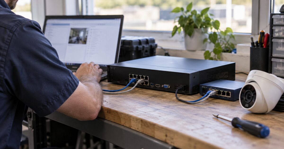
Quick answer: Start with camera power, the IP address plan and the correct NVR interface. Then check the camera login. DHCP is one part of the setup.
This guide walks installers and system integrators through IP addresses, DHCP and a few practical checks. DHCP can help with setup, but it will not fix a bad cable, the wrong VLAN or an incorrect camera password. If you are planning a system, review the available NVRs and confirm the requirements of the exact model.
On this page
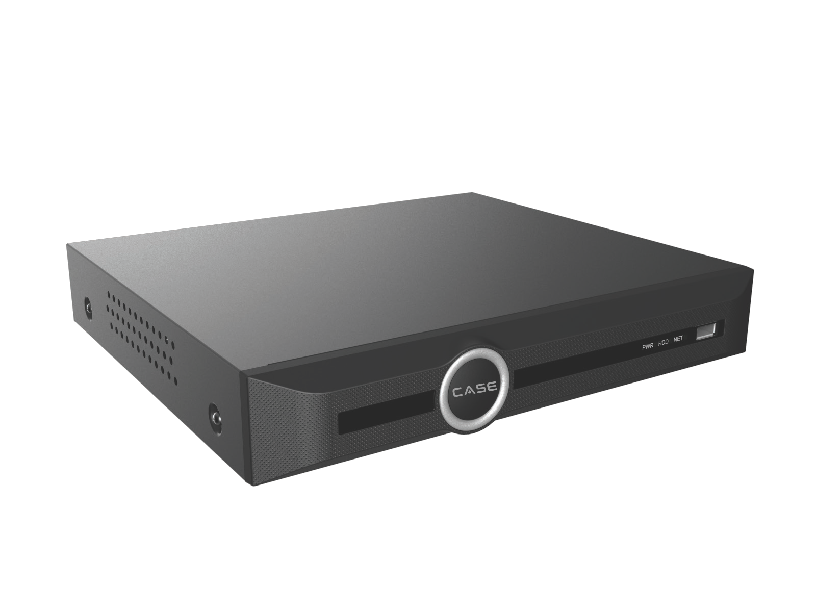
Start with these quick checks
- Check camera power and the Ethernet link. A lit PoE port is a useful clue, but it does not prove the camera is reachable. Try a known-good cable and check the switch’s PoE budget.
- Read the NVR’s camera status. Offline, wrong password and unsupported stream messages point to different problems.
- Write down the camera IP, subnet mask and the NVR interface that should reach it. Check for a duplicate IP address.
- Confirm the camera is activated and that the NVR has the correct camera credentials. These may be different from the recorder’s own login.
- Confirm the physical connection and VLAN. Cameras on an NVR’s built-in PoE ports may sit on a different network from its LAN port.
What DHCP does
DHCP lets a network service give a device an IP address and other network settings. That service may run on the site router or another server. It needs a valid network path to the device.
DHCP gives each enabled device its own network settings. If the cameras use static addresses, turning on DHCP on the NVR will not change them. Check the camera-side address plan before changing the recorder. DHCP does not activate cameras or supply their passwords.
For a small, flat camera network, DHCP can be a useful starting point. On a managed site, ask IT which VLAN and address plan to use before changing settings.
Check which camera network you are using
Cameras on an external PoE switch
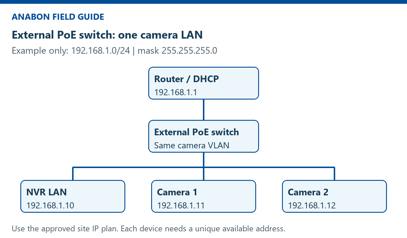
Check the switch uplink and the NVR’s LAN connection. In a simple setup without routing between networks, the camera and the NVR interface need addresses in the same subnet. If they are on different VLANs or subnets, IT must confirm routing and access rules. Automatic discovery may not cross those boundaries.
When choosing network switches, confirm the required PoE standard, available power and uplink capacity for the actual devices.
Cameras on the NVR’s built-in PoE ports
Some PoE NVRs use a separate internal camera network. The LAN interface and camera-side interface then have different jobs. Turning on DHCP for the LAN port does not necessarily change the internal camera network.
Check the recorder’s manual before changing camera addresses. Do not move a camera into the office LAN range just because the NVR’s LAN port uses that range.
Use a clear IP address plan
An IP address identifies a device’s network interface. The subnet mask tells the device which addresses are local. A default gateway is used to reach other networks; it is not what makes two devices on the same subnet talk to each other.
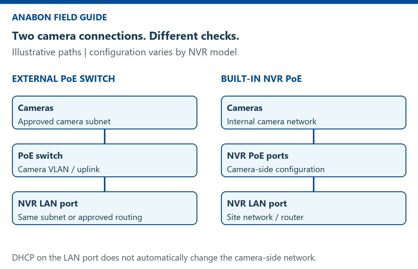
Example only: a camera LAN uses 192.168.1.0/24, with subnet mask 255.255.255.0.
| Device / interface | IP address |
|---|---|
| Router / gateway | 192.168.1.1 |
| NVR LAN interface | 192.168.1.10 |
| Camera 1 | 192.168.1.11 |
| Camera 2 | 192.168.1.12 |
In this /24 example, .0 is the network address and .255 is the broadcast address. Each device needs its own available address. Do not copy this plan onto a customer’s network without checking the existing devices and DHCP pool.
Private IPv4 ranges are 10.0.0.0–10.255.255.255, 172.16.0.0–172.31.255.255 and 192.168.0.0–192.168.255.255. These ranges do not tell you the site’s actual subnet mask, and using a private address is not a security control by itself.
For example, 192.168.1.10 and 192.168.0.11 are in different subnets when both use a /24 mask. Changing the last number alone is not enough if the network portion differs.
Enable DHCP on the correct NVR interface
Make this change during an agreed maintenance window, and keep local access to the recorder so you can reconnect if its address changes. Use the local monitor and recorder controls, or an approved management connection that already works. Menu names vary by model and firmware. Do not assume that an unknown default address will open the web interface.
- Record the current IP address, mask, gateway and interface selection before changing anything.
- Confirm with the site’s network administrator that DHCP is available on this interface’s VLAN.
- Open the NVR’s network settings and select the intended LAN interface. Check the manual if there is more than one interface.
- Enable DHCP and save. The recorder may receive a different address, so your current web session may disconnect.
- Read the new IP, subnet mask and gateway on the local recorder screen or in the authorised DHCP lease list. Reconnect using the new address.
- Check the camera list again. If a camera still has an address in another subnet, correct the approved address plan or the required routing; DHCP on the NVR alone will not resolve it.
If the NVR does not receive a valid lease, check the link, VLAN, DHCP availability and pool capacity with IT. Repeatedly switching DHCP on and off will not solve a missing network path.
Use the Download Center to find the appropriate model documentation and approved setup resources.
Keep addresses stable after setup
For a DHCP-capable device, IT can reserve an address against that interface’s MAC address. The device stays in DHCP mode, while the server keeps the agreed address for it.
A static address can also work. Use an address reserved for that purpose in the site’s plan and kept outside the dynamic DHCP pool, or explicitly excluded from it. Confirm the subnet mask, gateway and any required DNS settings.
Choose the method the site can maintain. Record each camera’s IP, MAC address, location and NVR channel. Keep credentials in the approved secure handover system, not in a public worksheet.
If the camera is still offline
No link or no power: check the cable, connector, PoE port and available power first.
Camera appears in discovery but will not add: check activation, the camera username and password, the selected protocol and the exact model’s supported integration.
Camera responds but live video fails: check stream settings, codec support, recorder capacity and the error message. Confirm the camera and NVR firmware combination before making changes.
Camera is on another subnet or VLAN: confirm the address plan, routing and firewall rules with IT. Do not bypass the site’s network controls.
Camera worked before and now fails: check whether its IP changed, whether another device is using that address, and whether the recorder still has the correct credentials.
A failed ping alone does not prove a camera is down; some devices or network rules block ICMP. Use the recorder’s status and an approved discovery or management tool as additional checks.
For mixed-brand installations, confirm support for the exact IP cameras, NVR, firmware and required functions. A general ONVIF label is not enough to confirm every feature.
Before you hand over the system
Confirm every expected channel shows live video and that a short test recording can be played back. Check the intended time zone and time synchronisation. Verify that addresses remain correct after an approved restart test.
Save the address plan and a short topology diagram. Note the exact models, firmware versions, camera locations and any routing or VLAN details. Follow the site’s backup and credential handover procedure.
Need help with the next step?
Send Anabon Technical Support the exact camera and NVR models, firmware versions, camera status message and a simple network diagram. Include the checks you have already tried, and remove passwords and unnecessary customer details from screenshots.
Related resources: Follow the installation and connection guide, or browse more setup walkthroughs in How To. For project equipment planning, explore Anabon’s product range. Return to the Surveillance Knowledge for more field guides.