


Smart Irrigation Planning: Sensors, Valves and Field Checks
Plan a smart irrigation project with soil measurements, valve checks, field connectivity and safe fallback rules. A practical guide for integrators.

By Anabon Security Inc. — Technical Support
On this page
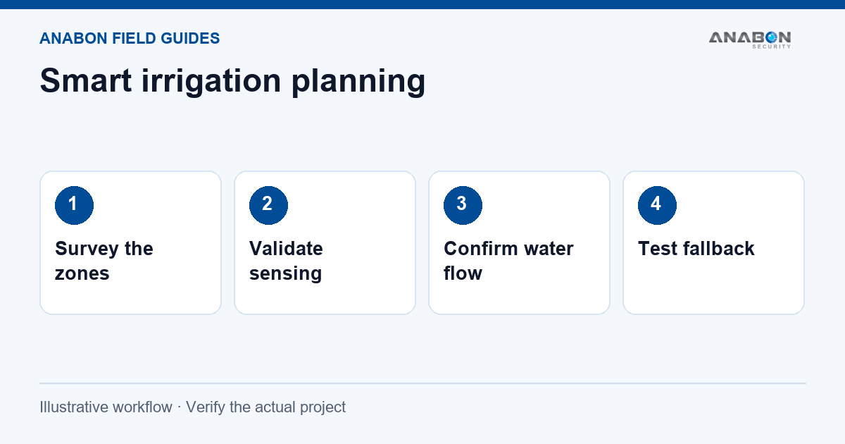
Start with the irrigation plan
A connected valve can make watering easier to manage, but it cannot decide the right irrigation plan on its own. Begin with the crop or planting area, soil conditions, available water supply and the advice of the person responsible for irrigation. The technology should support that plan.
Divide the site into zones with meaningful differences. A sunny slope, a shaded bed and a different soil type may not need the same schedule. Record the existing valves, pipe layout, pressure requirements and the way each zone is maintained before adding wireless control.
Check what the sensor is measuring
Choose sensor locations that represent the zone rather than the easiest place to install a probe. Confirm installation depth, contact with the soil, calibration guidance and protection of the cable or enclosure. A reading near a leaking emitter can be very different from conditions at the roots elsewhere.
Compare readings with field observations during the pilot. Look for changes after watering and rain, and check for a sensor that stops updating or reports an implausible value. Agree on what happens when the measurement is missing; missing data must not be treated as a dry-soil instruction.
Match the controller to the valve
Check the exact valve and solenoid requirements against the selected controller. Confirm the permitted voltage, current, latching or non-latching operation, wiring and environmental installation. A wireless controller name does not establish compatibility with the valve already in the ground.
| Item | Practical check |
|---|---|
| Electrical match | Read the controller and solenoid documentation; confirm the required supply and switching method. |
| Water path | Test the valve and line for the intended zone before automating them. |
| Flow feedback | Where flow feedback is part of the design, verify the meter and alarm rule with known conditions. |
| Manual access | Show the operator how to stop watering and use the agreed local fallback. |
Keep a clear distinction between a command sent, a command acknowledged and water actually flowing. Test which of those states the chosen system can report.
Survey field connectivity
The connection from the sensor or valve controller to the gateway is one part of the system. The gateway also needs the agreed power, backhaul and application connection. Test with real mounting heights, foliage and equipment positions, including difficult edges of the field.
The LoRa Alliance technical specifications are a reference for LoRaWAN technology; the actual coverage, message timing and device behavior depend on the selected equipment and deployment. Do not promise a distance from a brochure as site coverage.
If the gateway uses a cellular uplink, apply the same coverage and data-plan checks described in the solar and 4G planning guide.
Build rules with a safe stopping point
Agree on schedules, thresholds, maximum run times and the response to a leak or unexpected flow. Include weather and operational constraints where the chosen platform supports them. The irrigation lead should approve the rule values.
Start with a supervised zone. Watch a complete open-and-close cycle, verify the physical result and record the timestamps. Then test the approved fallback for loss of power or communication. Avoid repeated remote commands when the field state is unknown.
Use product references without borrowing promises
The Milesight smart water solution provides examples of soil monitoring and valve-control equipment. Confirm the current SKU, regional radio version, valve compatibility and application services for the actual order. Published case-study savings are not a forecast for a different field.
For a farm or yard that also needs video, plan that as a separate requirement. Browse solar security options or IP cameras only after defining the camera view, power and recording needs. An irrigation sensor is not a surveillance camera.
Document the pilot and handover
- Zone map, sensor locations and installation depths.
- Exact device, valve and firmware details; protected wiring and power arrangements.
- Approved schedule, thresholds, maximum run time and manual fallback.
- Test results for readings, commands, real water flow and loss of communication.
- Named owner for maintenance, alerts and seasonal changes.
Need help defining the equipment scope? Send the zone plan and required functions to Anabon Technical Support. Read IoT and AI project planning for the wider data-to-action workflow.
Related field guides
References: Milesight smart water solution · LoRa Alliance specifications.