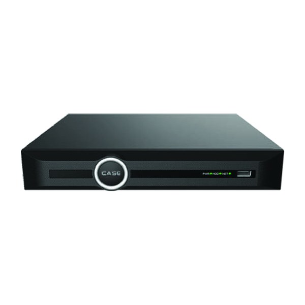



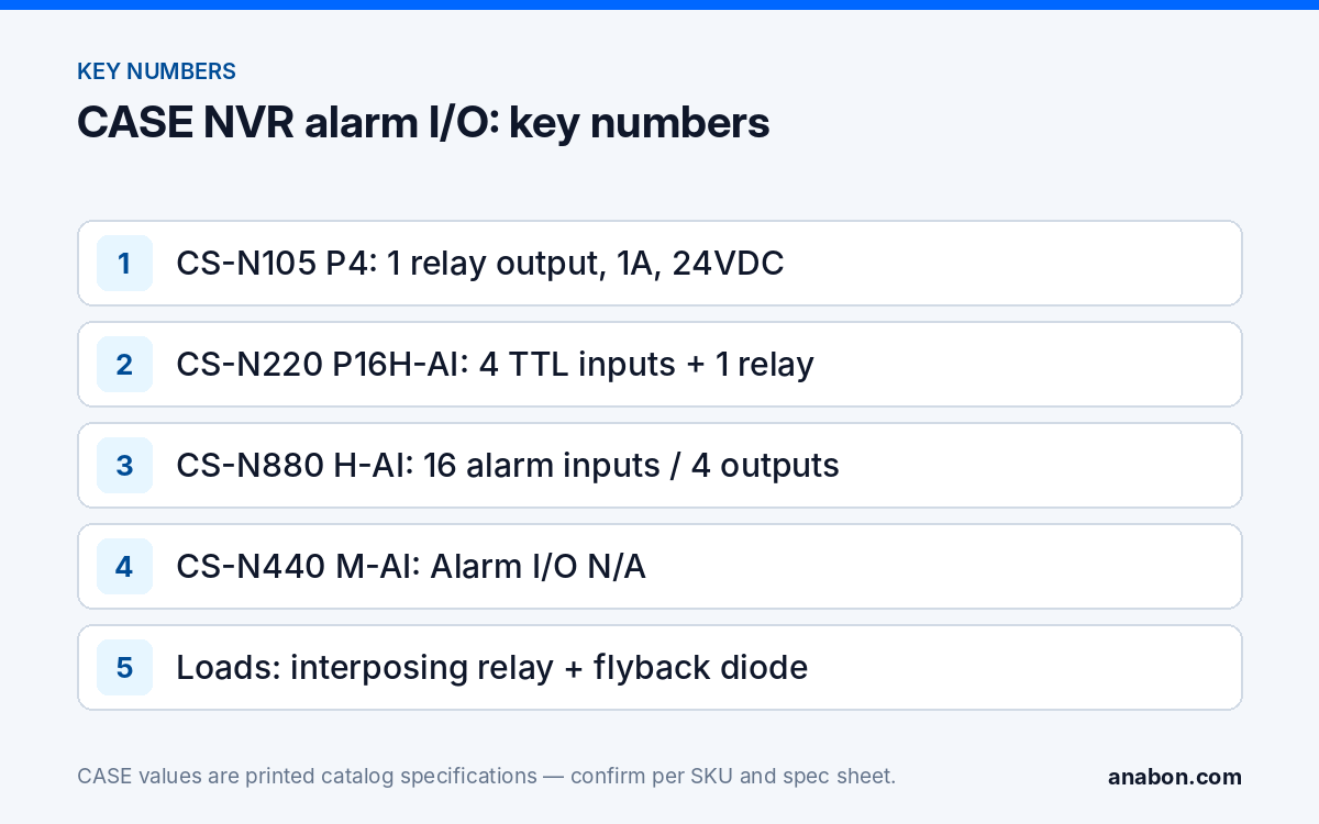
Quick answer: CASE NVRs print their alarm terminals per model: one relay output (1 A, 24 VDC) on the CS-N105 P4 and CS-N110 P8; four TTL inputs (3 mA, 3.3 VDC) plus that relay on the CS-N105 P4H-AI, CS-N110 P8H-AI and CS-N220 P16H-AI; 16 alarm inputs and 4 outputs on the CS-N440 P16H-AI, CS-N880 N and CS-N880 H-AI; none on the CS-N440 M-AI. Wire sensors as dry contacts, and never switch a siren’s or gate motor’s load through the NVR relay itself: drive an interposing relay or the device’s own trigger input.
Which CASE NVRs have alarm inputs and relay outputs?
The Alarm I/O row decides whether a recorder can take a door contact, a PIR or a loop detector, and whether it can switch a strobe, a siren or a gate operator. NVR alarm output wiring starts with this row, printed per SKU in the CASE Catalog 2027 Q1 and never carried across models.
| SKU | Alarm inputs (as printed) | Alarm outputs (as printed) |
|---|---|---|
| CS-N105 P4 | None printed | 1-ch relay output, 1A, 24VDC |
| CS-N105 P4H-AI | 4-ch TTL inputs, 3mA, 3.3VDC | 1-ch relay output, 1A, 24VDC |
| CS-N110 P8 | None printed | 1-ch relay output, 1A, 24VDC |
| CS-N110 P8H-AI | 4-ch TTL inputs, 3mA, 3.3VDC | 1-ch relay output, 1A, 24VDC |
| CS-N220 P16H-AI | 4-ch TTL inputs, 3mA, 3.3VDC | 1-ch relay output, 1A, 24VDC |
| CS-N440 M-AI | N/A | N/A |
| CS-N440 P16H-AI | 16 Alarm Inputs | 4 Outputs |
| CS-N880 N | 16 Alarm Inputs | 4 Outputs |
| CS-N880 H-AI | 16 Alarm Inputs | 4 Outputs |
Two gaps matter. The 40- and 80-channel units print counts only, with no input type or contact rating, so request the SKU spec sheet before sizing a load for those outputs; the 1 A, 24 VDC figure belongs to the smaller units. And the CS-N440 M-AI prints N/A: a 40-channel site that needs hard-wired I/O gets the CS-N440 P16H-AI or camera-side I/O (below); see choosing the right CASE NVR.
What do “TTL input, 3 mA, 3.3 VDC” and “relay output, 1 A, 24 VDC” mean on site?
A TTL input is a logic-level input: it idles at about 3.3 V and reads as active when something pulls it to ground, with 3 mA flowing through the closed contact. It is built for a dry contact (a switch, relay or reed contact between the input and the NVR’s alarm ground), not for a voltage. A 12 VDC or 24 VDC panel or PIR output goes through a relay first so the NVR only sees a contact closure.
A relay output is a contact inside the recorder that closes when an event rule fires. Its printed rating, 1 A at 24 VDC on the 5-, 10- and 20-channel units, is the maximum it may switch: another device’s trigger input or a small interposing relay coil, never 120 VAC line voltage (the same in the US and Canada), a motor, a large siren or an inductive load without a protection diode. A contact that switches more than its rating welds or burns, so size every load against the printed rating. CASE NVRs carry a 6-year warranty, handled through your dealer or approved business account.
Wiring basics: dry contacts, NO versus NC, and the ground reference
Alarm wiring on a camera system is a low-voltage, power-limited circuit: NEC Article 725 (Class 2) in the US, CEC Section 16 in Canada (verify the local code). Rules that hold on every job:
- Cable: 18 to 22 AWG stranded twisted pair, shielded where it shares a tray with power. A 500 ft (150 m) run of 22 AWG pair adds only about 16 Ω of loop resistance; noise and a missing common ground cause more faults than distance.
- Two wires per input: one to the numbered input, one to the NVR’s alarm ground (often labeled GND or G; read the silkscreen and the spec sheet).
- NC for supervision: wire door contacts and PIRs normally closed and set the input to NC in the NVR menu (names per model and firmware), so a cut cable shows as an alarm instead of silence.
- Isolation: nothing powered connects directly to an input. PIRs, loop detectors and panel outputs hand over a relay contact and take their 12 VDC from a separate supply.
- Label both ends and record the terminal assignment per your labeling and documentation standard.
How do I wire a siren or strobe to an NVR relay output?
The goal is a tripwire, perimeter or motion rule that fires an outdoor strobe or a short siren burst, with the recorder’s contact doing the switching and a proper supply doing the work. On a CS-N220 P16H-AI the relay is rated 1 A at 24 VDC as printed; strobes and sirens have inrush currents and coils that make direct switching poor practice even when the nameplate looks small.
- Power the siren from its own 12 VDC or 24 VDC supply, listed for the location (UL in the US / ULC in Canada), not from the NVR.
- Fit an interposing relay with a matching coil and wire the NVR relay output in series with it.
- Put a flyback diode across the coil (cathode to positive) so the coil’s collapse does not arc the NVR contact.
- Wire the siren through the interposing relay’s contacts, which are rated for its current.
- Link the event rule to the alarm output and set an output duration in seconds, not a latch; the range is per model and firmware.
- Test with a meter on the NVR contact first, then connect the load and trigger the rule from the camera’s view.
How do I trigger a gate from the NVR, and what must the NVR never be?
Gate operators accept a momentary dry contact on an open or free-exit input, and an NVR relay output can provide that pulse: a two-conductor run to the operator’s input terminals, output set to a short pulse. The trigger is a click in the NVR interface or a rule the recorder supports for that output, confirmed per model and firmware. Three boundaries:
- The operator’s own controller and entrapment-protection devices (photo eyes, edge sensors) remain the safety system, under its UL 325 listing in the US and its certification and the local code in Canada. A recorder is never a safety device.
- The NVR relay only requests an open; it never switches the motor or the operator’s power. Check the operator’s input against the printed 1 A, 24 VDC contact on the small units and the spec-sheet rating on the large ones.
- Do not promise plate-triggered opening. License Plate Search Support on the CS-N440 P16H-AI and License Plate Search on the CS-N880 H-AI are search functions for recorded plates, not an LPR trigger; LPR is confirmed per project with its own camera and documentation.
How do I wire a door contact or PIR into an alarm input?
The most useful scenario: a back door or cash-office door closes a contact, and the NVR records the covering channel, takes a snapshot and notifies the customer. A CS-N105 P4H-AI or CS-N110 P8H-AI gives you four TTL inputs, enough for the doors that matter on a small site.
- Mount a magnetic contact (NC) on the door, run a pair to the rack, and land it on alarm input 1 and the alarm ground terminal.
- Set input 1 to NC, name it (Rear door), and link it to event recording on the covering channel, a snapshot and an alarm notification.
- For a PIR, power it from a 12 VDC supply and bring its relay contact (NC) to input 2 and ground; keep its tamper loop on the alarm panel.
- Open the door: the alarm status should show the input active and the linked channel recording. Close it and confirm the input returns to normal.
The notification reaches the customer through CASE Connect, whose printed mobile functions include alarm information. CASE Connect is the official app experience for CASE systems. App features and remote access options should be confirmed by model, software version, and project configuration.
No I/O on the recorder? Use the camera’s alarm terminals
Several CASE cameras print their own alarm I/O, useful when the sensor is 300 ft (90 m) from the rack but 3 ft (about 1 m) from the camera, or when the recorder is a CS-N440 M-AI. The CS-I8XQ II-2.8mm and CS-I86V I-180 print Alarm I/O 1/1; the CS-I8MS I-2.7-13.5mm and CS-I8SS I-2.7-13.5mm print 2/1; the PTZ CS-P88 44X prints 8/2 (CASE PTZ cameras carry a 3-year warranty). Terminal ratings come from the SKU spec sheet, and whether the NVR acts on a camera-side input is confirmed per camera model, NVR model and firmware. Wire camera I/O in the junction box under the same rules.
Commissioning checklist for NVR alarm I/O
- Spec sheet read for the exact SKU; input type and contact rating on the drawing.
- Cable gauge, color code and routing chosen under NEC Article 725 / CEC Section 16 (verify the local code).
- Recorder powered down before terminals are landed.
- Every input tested from the field device, not by shorting the terminal at the rack; NO / NC confirmed with a cut-cable test.
- Every output tested with a meter before the load is connected, then with the load; durations in seconds, no undocumented latched outputs.
- Terminal assignment, device list and rule list recorded in the commissioning report.
What to tell your customer
“Your recorder can take signals from door contacts and motion sensors, and it can switch a strobe or send an open request to the gate controller. We wire those through proper relays, so the siren and the gate keep their own power supplies and safety devices. When a door opens after hours you get a notification and a clip, and the event is logged.” For warranty and service, please contact the installer or company that supplied your system.
FAQ
Can the NVR relay output drive a siren directly?
Only within the printed rating, which is 1 A at 24 VDC on the CS-N105 P4, CS-N110 P8 and the 5-, 10- and 20-channel AI units, and only for a resistive load. Sirens and strobes draw inrush current and many contain coils, so the reliable design is an interposing relay with a diode across its coil, powered from the siren’s own supply.
Can I connect my alarm panel’s 12 V output to a TTL alarm input?
No. The TTL inputs on the CS-N105 P4H-AI, CS-N110 P8H-AI and CS-N220 P16H-AI are printed at 3.3 VDC and 3 mA and expect a dry contact to ground. Feed the panel’s voltage output into the coil of a small relay and bring that relay’s contact to the NVR input. The relay also isolates the two systems’ grounds.
Which CASE NVR has the most alarm inputs and outputs?
The CS-N440 P16H-AI, CS-N880 N and CS-N880 H-AI each print 16 Alarm Inputs / 4 Outputs. The catalog row prints counts only; the input type, the output type and the contact rating are on the SKU spec sheet, so request it from Anabon before you design loads for those outputs or specify them in a bid.
Does the CS-N440 M-AI have any alarm inputs or outputs?
No; the catalog prints Alarm I/O N/A for that model. If a 40-channel site needs hard-wired I/O, specify the CS-N440 P16H-AI, which prints 16 inputs and 4 outputs, or use cameras that print their own alarm terminals, such as the CS-I8MS I-2.7-13.5mm at 2/1, with the NVR-side behavior confirmed per model and firmware.