


Quick answer: A standard PoE link is good for 328 ft (100 m) of Cat5e or better, end to end, because IEEE 802.3 and ANSI/TIA-568 both stop there. Past that you have four tools: an extend-mode port such as the 820 ft (250 m) Extend Mode printed for CS-H1108PLS (fixed cameras, lower link rate), a PoE extender within 328 ft (100 m) of the source, fiber to a remote PoE switch with local power, or, with no trench possible, a solar tower with a 4G router, quoted per project.
Why 328 ft (100 m)? The IEEE and TIA limits
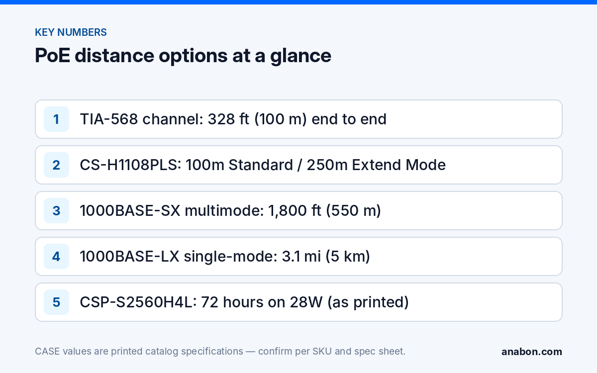
The limit is written into two standards that every PoE camera depends on. IEEE 802.3 specifies 100BASE-TX and 1000BASE-T over 328 ft (100 m) of twisted pair, and ANSI/TIA-568, the cabling standard used in the US and Canada, defines the channel as 328 ft (100 m): 295 ft (90 m) of permanent link plus 33 ft (10 m) of patch cords combined. Attenuation and timing are specified for that length and no further, which is why a certifier will not pass a longer link.
PoE adds a second reason. The IEEE power figures assume a maximum DC loop resistance over the channel: 20 Ω for 802.3af, 12.5 Ω for 802.3at. That is where the gap between 15.4 W at the port and 12.95 W at the camera (af), or 30 W and 25.5 W (at), comes from. Double the cable and you double the resistance; a powered device that needs 42.5 V minimum (802.3at) can drop out under load while a tester on an unloaded line still reads fine. The CS-PSE3301AC injector prints the same boundary, “1000Base-T Cat5e or higher (≤100m)”. Measure the real route, service loops and patch cords included: a certifier reading of 312 ft (95 m) leaves 16 ft (5 m) for both patch cords, which is rarely enough.
Extend mode on CASE switches: what changes at 820 ft (250 m)
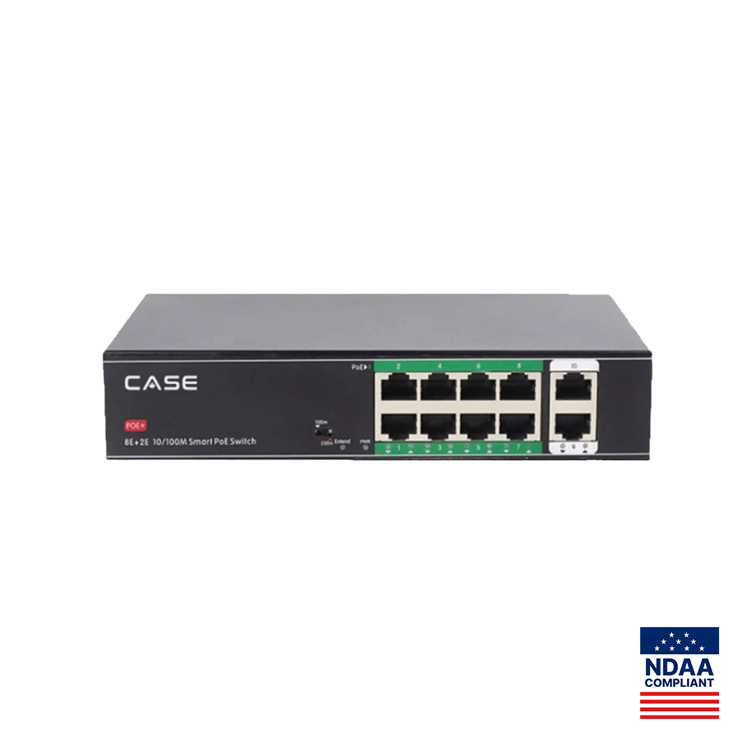
CS-H1108PLS prints a transmission distance of “100m (Standard) / 250m (Extend Mode)”, 8×10/100M PoE ports with 2×10/100M uplinks, IEEE802.3af/at, 30 W per port and a 100 W total budget. Three things change when you use the 820 ft (250 m) mode.
- Link rate. Extend mode in this class of switch negotiates the port down to a low fixed rate, commonly 10 Mbps; the catalog does not print the rate, so confirm it on the switch documentation. At 10 Mbps, one 5MP camera at 4 Mbps fits and two cameras at 3 Mbps each are near the ceiling once overhead is counted. Extend mode is for one or two fixed cameras per port, not a PTZ with a 4K main stream.
- Power at the camera. Scaling the IEEE 12.5 Ω assumption to 820 ft (250 m) gives roughly 31 Ω of loop resistance. At the 802.3at limit of 600 mA the cable alone drops about 18 V, pulling the far end below the 42.5 V minimum; at a fixed camera’s few watts (around 0.13 A at 48 V) the drop is about 4 V and the camera runs. This is an estimate from the IEEE figures, not a CS-H1108PLS specification, and it is why extend mode suits fixed cameras, not bt-class PTZs such as CS-P48 63X or CS-P88 44X, which need their own supply or a bt injector at any distance (see PoE camera not powering on).
- Testing. A link longer than 328 ft (100 m) cannot be certified to ANSI/TIA-568. Document it as an extend-mode link, test it with the actual camera at its real bitrate, and log the PoE tester reading at the camera end at night with illuminators on.
Use solid-copper Cat6 (23 AWG) rather than Cat5e for any extend-mode run; the lower resistance buys back voltage. Copper-clad aluminum fails on these runs first and is not recognized under ANSI/TIA-568.
PoE extenders: when and how
A PoE extender is a small repeater that takes power from the PoE line, regenerates the Ethernet signal and passes power onward. It needs no local AC, so it fits in a junction box on a pole halfway along the run.
- Place the first extender within 328 ft (100 m) of the switch; each one adds up to another 328 ft (100 m). Two hops, 984 ft (300 m) total, is a sensible ceiling; past that, use fiber.
- The extender consumes a watt or two itself and often passes a lower class downstream; check its input and output classes against the camera’s spec-sheet draw and the port’s 30 W maximum on the CASE switches.
- Unlike extend mode, a good extender keeps the link at 100 Mbps or 1 Gbps, so bitrate is not the constraint.
- Outdoors, it goes in a rated enclosure; its temperature range matters as much as the camera’s in a northern winter.
- CASE does not print an extender in the catalog; the model is specified and confirmed per project.
Fiber for long runs: SFP uplinks and media converters
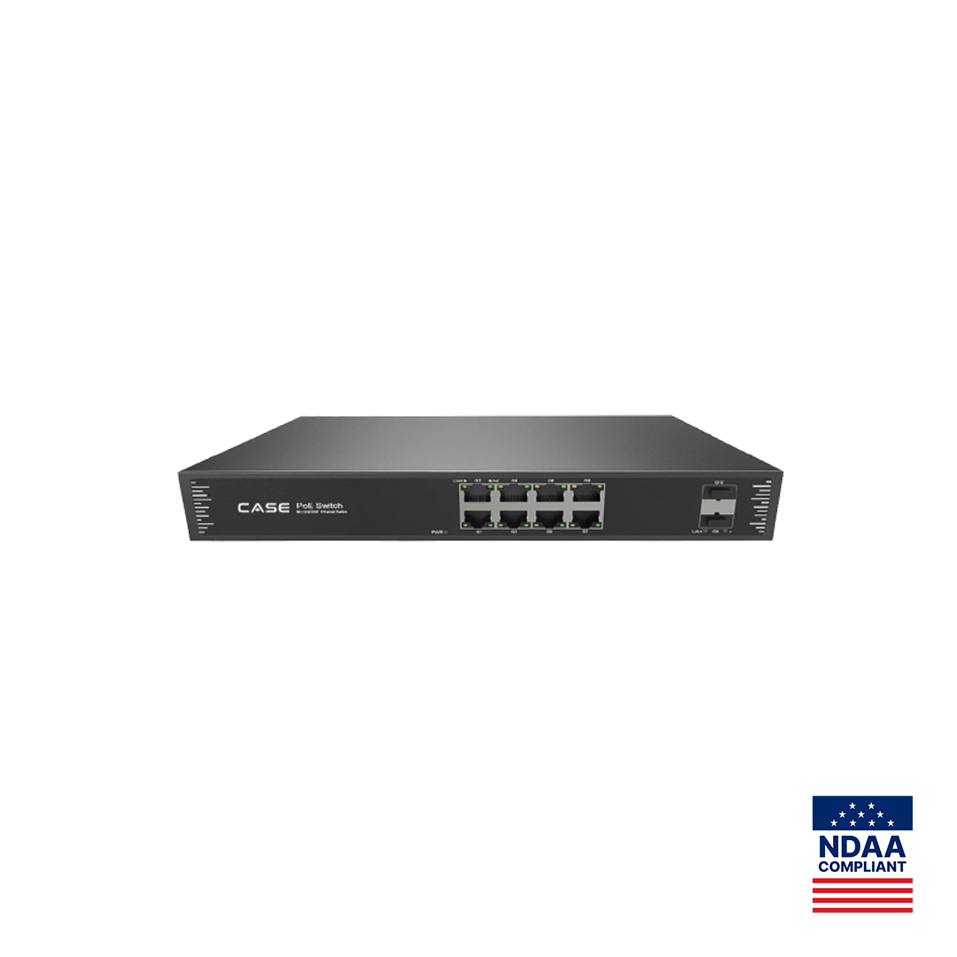
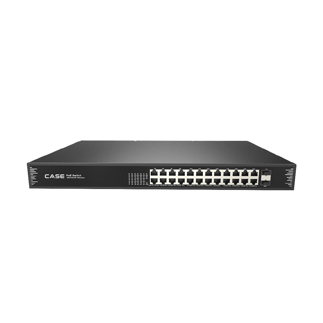
Once a run exceeds what two extenders cover, or crosses between buildings, fiber is the answer, and two CASE switches are built for it. CS-POE33108PF prints 8×10/100/1000M RJ45 PoE ports with 2×1000M SFP fiber ports and a 130 W / 250 W budget; CS-POE33024PF prints 24×10/100/1000M RJ45 PoE ports with 2×1000M SFP fiber ports and a 400 W / 600 W budget. The pattern: head-end switch, SFP module, fiber, SFP module, remote PoE switch, cameras on copper within 328 ft (100 m) of that remote switch.
| Fiber link | Fiber type | Reach per IEEE 802.3 | Typical use |
|---|---|---|---|
| 1000BASE-SX | Multimode (OM2 and above) | 1,800 ft (550 m) | Across a yard, parking structure or warehouse floor |
| 1000BASE-LX | Single-mode | 3.1 mi (5 km); longer-reach modules confirmed per module | Between buildings, across a campus, along a fence line |
Four design notes. The SFP modules on both ends must match in mode and wavelength; the catalog does not print which modules the switches support, so they are specified per project. The remote switch needs local power: both switches print AC 100–240V input, −4 °F to 131 °F (−20 °C to 55 °C) and IP30, so outdoors they live in a rated, heated or ventilated cabinet. Fiber carries no electricity, so a link between buildings brings no ground-potential difference and no lightning path into the rack; copper between structures does, and needs surge protection and bonding under the NEC (US) / CEC (Canada), so verify the local code. Where the far end has only a copper switch, a pair of media converters does the same job, powered at each end.
Beyond cable: solar and 4G for sites with no trench
Some camera positions have no cable path at all: a gravel lot, a construction perimeter, a remote gate. The options are a point-to-point wireless bridge back to a building with power and network (specified per project), or a self-powered tower with cellular backhaul. The CASE Project Series includes the CSP-S2560H4L compact solar surveillance tower, which prints a 1×450W bifacial panel, a 2560Wh LFP battery, 24V/48V available voltage, an 11.5 ft (3.5 m) hot-dip galvanized mast with manual winch, a base with forklift holes, 794 lb (360 kg) weight, and a running time of 72 hours on 28W. Its optional accessories row prints POE, 4G router, NVR and cameras; the 8-port PoE row prints NO, so the power and network layer is configured per project.
Two design rules make these towers work. Keep the load inside the printed figure: 28 W is one fixed camera plus a router and a small recorder, not a laser PTZ with illuminators running all night. And record at the tower, not across the 4G link: cellular upload is the scarce resource, so use it for live view and alarms. CSP-S2560H4L is a Project Series item: availability, lead time, certificates and warranty term are confirmed in writing per project before anything is promised. Send the site plan through the contact page.
Decision table: distance to solution
| Run length | Solution | Link rate | Power at the camera | Notes |
|---|---|---|---|---|
| Up to 328 ft (100 m) | Standard PoE port | 100 Mbps or 1 Gbps | Full class (af/at on CASE switches) | Certifiable to ANSI/TIA-568; the default |
| 328–984 ft (100–300 m) | One or two PoE extenders, the first within 328 ft (100 m) | Full rate | Reduced by each extender | No local power; enclosure outdoors; two hops maximum |
| 328–820 ft (100–250 m) | Extend Mode on CS-H1108PLS | Low fixed rate (confirm) | Fixed cameras only | Not certifiable; test with the real camera at night |
| Up to 1,800 ft (550 m) | Multimode fiber (1000BASE-SX) to a remote PoE switch | 1 Gbps | Full class from the remote switch | Remote switch needs AC and a cabinet |
| Up to 3.1 mi (5 km) and beyond | Single-mode fiber (1000BASE-LX or longer-reach) to a remote PoE switch | 1 Gbps | Full class from the remote switch | Dielectric; no lightning path between buildings |
| No cable path | Wireless bridge, or CSP-S2560H4L solar tower with 4G router | Wireless or cellular | Tower battery (72 hours on 28W as printed) | Project Series: confirmed in writing per project |
For a site that combines most of these, see parking lot security cameras; PoE switches and solar solutions are on shop.anabon.com (business account login).
What to tell your customer
“Network cable carries camera power and video for 328 ft (100 m) by standard. Three of your camera positions are further than that, so we are using fiber to a small powered switch near those poles rather than stretching copper past its limit. It adds a little hardware and removes the night-time dropouts that come with over-length runs.” For a solar tower, say only what is confirmed in writing for the project: warranty term, lead time and certificates for Project Series items are confirmed per project.
FAQ
What is the maximum distance for a PoE camera?
328 ft (100 m) of Cat5e or better, end to end, including patch cords, under IEEE 802.3 and ANSI/TIA-568. Beyond that you need an extend-mode port, a PoE extender, fiber to a remote PoE switch, or a wireless or solar solution. An injector such as CS-PSE3301AC does not extend the distance; it prints the same 328 ft (100 m) limit.
Does CS-H1108PLS really reach 820 ft (250 m)?
The catalog prints “100m (Standard) / 250m (Extend Mode)” for CS-H1108PLS. Extend mode lowers the link rate, so it suits one or two fixed cameras per port, and the voltage at the far end falls as the camera’s current rises, so it is not for PTZ cameras. Confirm the extend-mode rate on the switch documentation and test with the real camera at night.
PoE extender or extend mode: which should I use?
Use an extender when you need full link speed or a higher-draw camera and can mount a box within 328 ft (100 m) of the switch. Use extend mode when the run is up to 820 ft (250 m), the camera is a fixed model at a few watts, and there is no midpoint for an extender. Past 984 ft (300 m), use fiber.
Which CASE switches have fiber ports?
CS-POE33108PF (8 Gigabit PoE ports, 130 W / 250 W) and CS-POE33024PF (24 Gigabit PoE ports, 400 W / 600 W) each print 2×1000M SFP fiber ports. SFP modules and fiber type are specified per project; the remote switch needs AC power and, outdoors, a rated cabinet, since both print IP30 and −4 °F to 131 °F (−20 °C to 55 °C).