


Quick answer: An existing pole or corner is a candidate only after ownership, structural capacity, view, permitted cable route and reliable power are confirmed. Check the actual mount compatibility and power/data design before promising no trenching. Standard Ethernet planning and a model-specific extended mode are different cases. A wide camera may help, but neither one housing nor a 180° label guarantees two-camera coverage, one NVR channel or usable detail everywhere.
On this page
What makes an existing pole worth assessing?
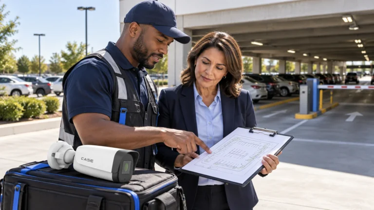
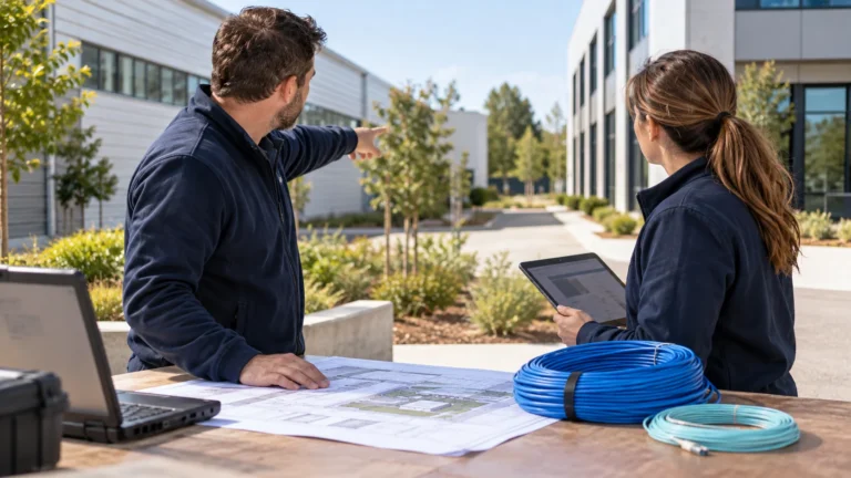
Reusing a suitable structure and approved pathway may reduce civil work, but survey it before putting a no-trench promise in the quote. A standing light pole does not establish ownership, spare conduit, continuous power, safe added load or useful camera height. Compare the full installed and maintained options, including any electrical, structural or access work. Parking lot security cameras covers scene layout; this guide covers whether the existing structures can safely serve it.
Using existing light poles: ownership, circuit, material and sway
Before a bracket is quoted, answer four questions about each pole; any one of them can rule it out.
- Permission: verify the pole/landowner and obtain the required attachment, access and work approvals; location on the lot does not establish ownership.
- Power: have the responsible qualified person identify the actual circuit, switching and required service hours/continuity. Do not assume a lighting feed stays live.
- Structure and view: assess pole material, condition, foundation, added load, wind/ice and vibration for the actual bracket and target. A wide lens is not immune to sway.
- Route: verify a permitted usable cable path, separation and maintenance access. No hand hole or spare conduit does not by itself decide between wireless and trenching.
CS-A36 is listed as a pole mount; verify the full camera/bracket combination, pole dimensions, load and fastening method on the actual specification sheets and installation instructions. Measure the pole, then obtain the pole owner/manufacturer’s approved attachment method. Do not assume banding, drilling or a below-luminaire position is universally suitable. Plan approved weatherproof entries, cable restraint, access, bonding and surge protection with the responsible designers; see outdoor cable entry and weatherproofing and lightning/surge planning.
Power options on a pole: which one for which distance?
The ways to get data and power up the pole differ by distance, by who does the work and by what the customer maintains afterward.
| Option | Assess before selecting | Limits to verify | Responsible work |
|---|---|---|---|
| Standard copper PoE | Actual total channel length, pathway, cable, temperature and camera demand | Plan the applicable 100m channel including patching; verify per-port and total power and required bitrate | Qualified cabling/electrical roles as required locally |
| CS-H1108PLS Extend Mode | Exact approved cable, powered device and installed length | Printed 100m standard/250m Extend, 8×10/100M PoE, 30W per-port maximum and 100W total budget do not guarantee 30W at a 250m device. Confirm mode speed, losses, peak load and final stability | Designer/installer following the actual device instructions |
| CS-PSE3301AC injector with local power | Approved circuit, enclosure and thermal/condensation design | Printed 802.3af/at, 15.4W/30W and −20°C to +55°C; adding a weatherproof box alone does not establish outdoor suitability | Qualified electrical work plus approved network installation |
| Fiber to an approved cabinet | Fiber, compatible SFP/conversion equipment, local power and environmental requirements | CS-POE33024PF lists two 1000M SFP uplinks; confirm actual modules, fiber, endpoints and power separately | Approved fiber/network and electrical design |
| Wireless bridge | Surveyed path, clearance, link budget, interference, permitted equipment and security | Line of sight alone is insufficient; verify capacity, uptime needs, power, weather and maintenance | Responsible radio/network designer and installer |
Confirm the applicable electrical, communications, structural and permitting requirements with the responsible qualified local reviewer. Existing lighting conduit is not automatically an approved communications route; conductor separation and pathway use need verification. Do not open or alter line-voltage equipment without the required authorization and qualification. PoE distance planning explains the separate cable, power and bandwidth checks; no-trench claims remain conditional until the actual route is approved.
Corner mounts: two directions from one position
An outside corner can provide useful mounting options, but check the actual desired views, obstructions and approved cable route. CS-A35 is listed as a corner mount; its actual camera/bracket compatibility, load, fasteners, substrate and sealing need the applicable instructions and structural approval. Do not infer compatibility or a universal fixing detail from the accessory name alone.
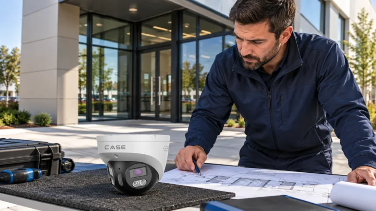
Draw the actual two facade/lot views from the proposed mounting point. Use documented FOV and physical occlusion, not a universal corner-angle calculation. Separate cameras may suit different directions and target distances; a panoramic camera may suit the area in front of it without seeing along both walls. Verify both extremes and the join on site. Housing choice is a separate decision in bullet vs dome vs turret.
When can a panoramic view serve this position?
CS-I86V I-180 lists an 8MP (4+4) stitched sensor arrangement, fixed 2.8mm lens, 4640×1728@25fps, 30m maximum IR and 30m white light, microphone/loudspeaker, 1/1 alarm I/O, IP67, Metal housing and −35°C to +65°C operation. Those rows describe the product, not a two-camera replacement guarantee. Verify the actual view, recorded detail, channel/license behavior, power and required event/output functions for the proposed integration.
| Decision | Separate task views | CS-I86V I-180 wide view |
|---|---|---|
| Physical installation | Count actual cameras, compatible mounts, cables and power needs | One housing may reduce physical hardware where its tested view meets the task |
| Recorder and licenses | Verify actual required streams, channels, bandwidth and event paths | A stitched frame alone does not prove one channel/license or every required recording mode |
| Coverage | Test overlap, gaps, occlusions and each target distance | Test both ends, join artifacts and occlusions; no automatic gap-free result |
| Night evidence and response | Verify each exact model and final illumination | Printed light/low-light rows do not guarantee identity or a supported deterrence sequence |
| Faces and plates | Choose task-specific views and test recorded targets | A 2.8mm label alone establishes neither success nor failure at an unspecified distance |
A wide overview distributes detail across the scene, so verify required target positions and retain dedicated entrance or plate views wherever the evidence task is not met. Do not choose by pixel count, focal-length label or an assumed camera-count saving alone. Confirm AI/client functions and the actual response path. Stitched versus non-stitched designs are covered in 180° panoramic cameras. Confirm the written warranty and exclusions for the exact supplied camera and accessories.
Height, angle and lighting on the pole
Choose height and angle from required target detail, permitted access, vandalism risk, obstructions and the approved structure. No universal 12–16ft height or horizon position proves the view; test moving targets in the final recording, including sway where relevant. Survey real lighting, headlights, shadows and seasonal conditions. A 0.0009 Lux row or PhotonX name is not a moving-face or plate guarantee, and a lighting recommendation alone does not prove the camera’s night result. Use the camera mounting-height guide to plan the recorded task and access checks.
What to tell your customer
We will use existing poles and corners where permission, structure, view and the approved power/data route support the design. The proposal will state any civil work and unresolved survey conditions. We will test the required recorded targets, night lighting and integration before accepting a camera-count saving or no-trench option. Service and warranty follow the supplied equipment’s written terms.
FAQ
Can I power a security camera from a parking lot light pole?
Possibly, after the owner and a qualified person confirm the actual circuit, switching, capacity and required service continuity. A light pole does not establish a 24-hour supply. If continuous recording is required, provide the approved continuous power arrangement; compare a suitable PoE feed or another designed option. Do not alter line-voltage equipment based on this article.
How far can PoE reach a pole camera without a new switch at the pole?
Plan standard Ethernet against the applicable 100m total channel, including patching and the actual cable/power conditions. CS-H1108PLS prints 250m in Extend Mode, but distance and 30W-per-port maximum rows do not prove delivered power or bitrate at that length. Obtain the exact mode limits and test the installed cable, peak device load and complete workload before selecting it. Fiber or another approved architecture may fit better.
Does one 180° camera really replace two cameras on a pole?
Only if its tested coverage, recorded target detail and actual integration meet both tasks. One housing or stitched 180° image does not prove no blind area, one recorder channel/license or adequate plate/face detail. Verify the join and both ends, actual event/recording modes and each target position; keep additional task views where needed. The 180-degree panoramic camera guide explains the overview and task-view trade-offs.
When is a wireless bridge justified for a pole camera?
When a surveyed, approved radio design meets the required capacity, availability and security and compares favorably with a permitted cable/fiber route. Check path and clearance, changing obstructions, interference, local radio requirements, power, equipment ratings and ongoing access/maintenance. Clear line of sight and two radios alone do not establish a reliable link.
References
- Anabon: exact-model manuals, firmware and installation documents
- Cisco: standard PoE power delivery, losses and 100m planning
- Anabon: panoramic coverage and integration checks